Lesson Four – Button Input for LED

As we know, the flashlight needs a switch to control the LED’s on and off. This circuit adds a button to the basic LED circuit and cooperates with the code to achieve this function.
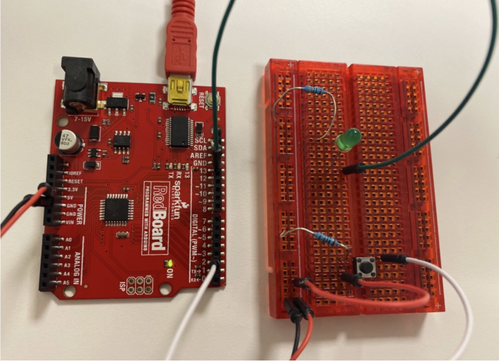
What way it may look like if you build this circuit with an Arduino kit:
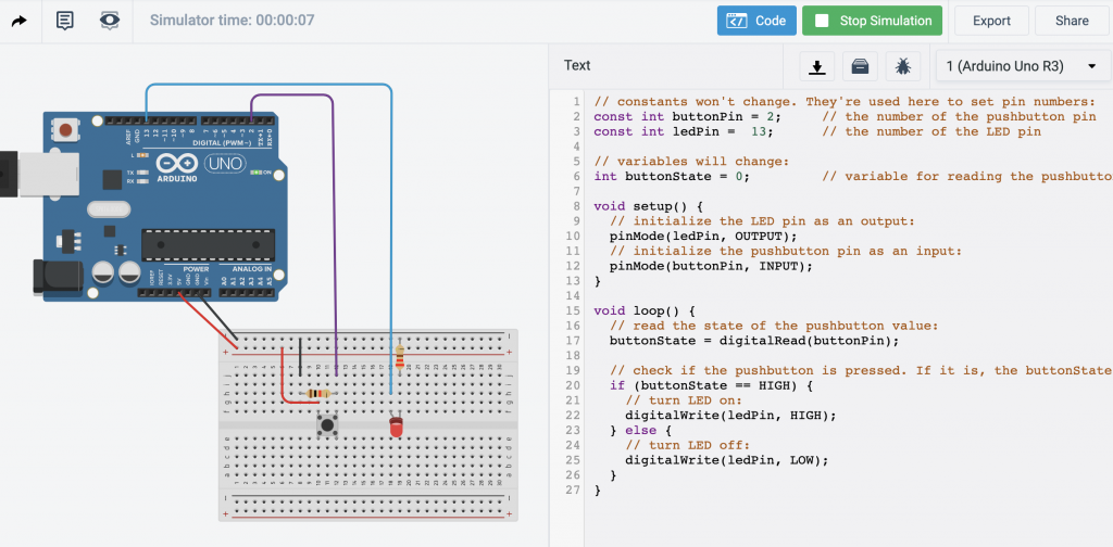
Try to build this circuit in Tinkercad Circuits:
STEP 1: Find the Sample Code
The code for this project can be found: File > Examples > 02. Digital > Button

Look closely at comments to see how the code works.
// constants won't change. They're used here to set pin numbers:
const int buttonPin = 2;     // the number of the pushbutton pin
const int ledPin =  13;      // the number of the LED pin

// variables will change:
int buttonState = 0;         // variable for reading the pushbutton status

void setup() {
  // initialize the LED pin as an output:
  pinMode(ledPin, OUTPUT);
  // initialize the pushbutton pin as an input:
  pinMode(buttonPin, INPUT);
}

void loop() {
  // read the state of the pushbutton value:
  buttonState = digitalRead(buttonPin);

  // check if the pushbutton is pressed. If it is, the buttonState is HIGH:
  if (buttonState == HIGH) {
    // turn LED on:
    digitalWrite(ledPin, HIGH);
  } else {
    // turn LED off:
    digitalWrite(ledPin, LOW);
  }
}
STEP 2: Connect one side of the button to the “+”
Use a jump wire between the “+” and one of the button’s legs

STEP 3: Connect the second leg of the button to Pin 2

STEP 4: Add 1K Ohm Resistor- NOT 220 Ohm
Connect the resistor to the second leg of the button. Other side connect to the “-” bus

STEP 5: Build an independent loop with the LED
Connect the pin 13 to any unoccupied row, and the circuit could look like this :

STEP 6: Test the Code
After we paste the code and start the simulation, when you press the button, both the onboard LED and the LED on the breadboard will light up!