Lesson Three – Dimming an LED

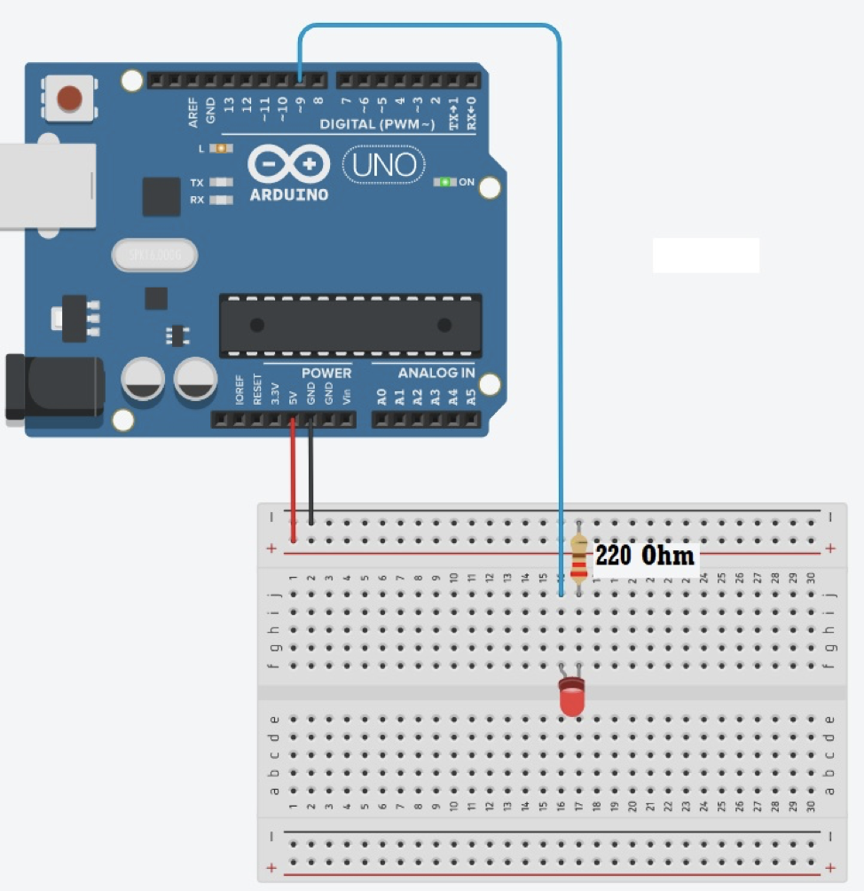
What way it may look like if you build this circuit with an Arduino kit:

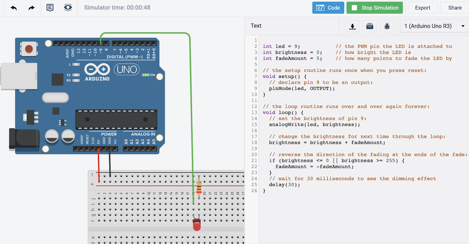
Try to build this circuit in Tinkercad Circuits:
STEP 1: Find the Sample Code in Arduino
The code for this project can be found: File > Examples > 01. Basics > Fade
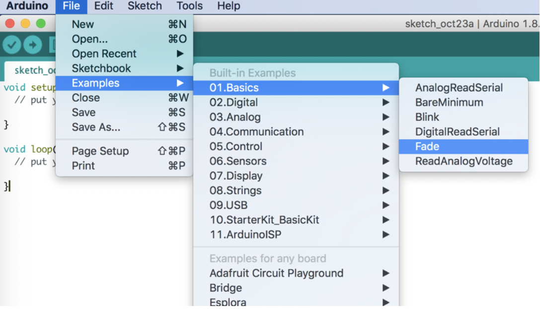
Look closely at comments to see how the code works.
“analogWrite” means we will be using pin 9 for PWM (Pulse Width Modulation).
PWM is used to quickly turn off and on a light or a motor in order to dim or slow the device. Only pins with a “~” will work for this.
int led = 9;           // the PWM pin the LED is attached to
int brightness = 0;    // how bright the LED is
int fadeAmount = 5;    // how many points to fade the LED by

// the setup routine runs once when you press reset:
void setup() {
  // declare pin 9 to be an output:
  pinMode(led, OUTPUT);
}

// the loop routine runs over and over again forever:
void loop() {
  // set the brightness of pin 9:
  analogWrite(led, brightness);

  // change the brightness for next time through the loop:
  brightness = brightness + fadeAmount;

  // reverse the direction of the fading at the ends of the fade:
  if (brightness <= 0 || brightness >= 255) {
    fadeAmount = -fadeAmount;
  }
  // wait for 30 milliseconds to see the dimming effect
  delay(30);
}
STEP 2: Wiring the Circuit
NOTICE: For this project, connect the positive leg of your LED to digital output pin 9 on your board, and the circuit could look like this:
After we paste the code, and start the simulation , the LED on the breadboard should fade off and on.
Bonus:
Alter the code to change speed of the fade.

So the “delay” at the end of the code controls the speed of the fade.
Try changing the value of the delay and see how it changes the fading effect!