Basic Circuitry Knowledge
Circuits as loops
A circuit needs to be a full path. The loop starts and ends at your power source. The sum of voltages in a loop equals zero. The power source is considered positive so any drops across loads, such as resistors or LEDs, are negative. In the image below the battery has 9V across and you can consider the resistor as -9V.
The schematic diagram and real circuit shown below are examples of series circuits. They are series circuits because a single current flows through every component.
Jumper Wires
Convenient lengths of wire that are crimped on both ends. They are great for prototyping.
Breadboard
A circuit board used to test circuitry. Generally, the power source is connected to the red section on the positive side and the blue on the negative. Each colored line is internally connected so they act as voltage distribution.
The schematic diagram and breadboard image below are examples of parallel circuits. They are parallel circuits because the current splits, with some flowing along each parallel branch.
Parallel vs. Series Circuits
There are two basic ways in which to connect more than two circuit components: series and parallel. In a series circuit, a single current moves through all components in the circuit, while in a parallel circuit the current splits, with some flowing along each parallel branch and re-combining when the branches meet again. The voltage across each resistor in parallel is the same.
In a series circuit, failure of a single component can disable all components in the circuit. In a parallel circuit, failure of one component will still allow other components to operate.

See the below image of Christmas lights, can you tell the difference between series circuits and parallel circuits?
Terms:
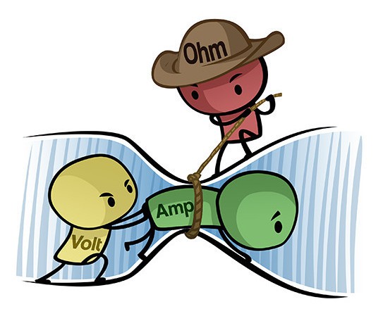
- Voltage (Volts) – V: Electrical potential; the force that makes electricity move
- Current (Amps) – I (not C): Actual flow of electrical energy
- Resistance (Ohms) – R: Opposition or blocking of electrical flow/current
- Power (Watts) – P: How much energy is transferred per second
All units are expressed using the metric system, so 1 watt/ohm/amp/volt=1000 milliWatts/milliOhms/milliAmps/milliVolts

Ohm’s Law
Ohm’s law states the interrelationships between these four parameters.
V = I * R
Voltage equals Current times Resistance (remember, current is abbreviated as I)
Can be restated as I = V/R or R=V/I
P = V * I
Power is Voltage times Current
Can be restated as P = R * I2 or P = V2 / R
With the relationships between these parameters, you can solve for any if you have 2 of them. Be careful to keep track of units!
Ohm’s law calculation examples
Example #1 – Resistor Power
Voltage = 5 volts, Resistance = 100 Ohms
I = V/R, I = 5/100, I = 1/20 Amps, I = 0.05 Amps
P = V2/R, P = 52/100, P = 1/4, P = 0.25 Watts
Example #2 – LED Power
Voltage = 5V, Current = 20mA
R = V/I, R = 5/0.02, R = 250 Ohms
P = V*I, P = 5*0.02, P = 0.1 Watts or 100 mW
| Introduction |
| Lesson One: System Design |
| Lesson Two: Basic Circuitry Knowledge |
| Lesson Three: Electronics Tools |
| Lesson Four: Lighting an LED |
| Lesson Five: Tilt Switch |
| Lesson Six: Photoresistor and LED |
| Lesson Seven: Button with Piezo Speaker |
| Lesson Eight: Dimming an LED |
| Lesson Nine: Button Input for LED |
| Lesson Ten: Ultrasonic Sensor Alarm |
| Further Resources |