Lighting an LED
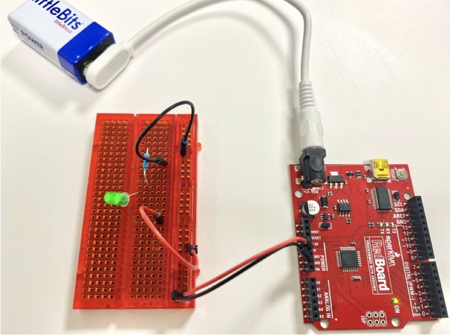
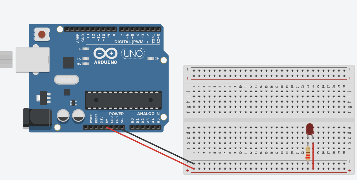
We can build a very simple but versatile circuit, which exists in your flashlight, table lamp, and many other home appliances. Below is an example of what it would look like if you build this circuit with an Arduino kit. We will build this step-by-step in TinkerCad Circuits:
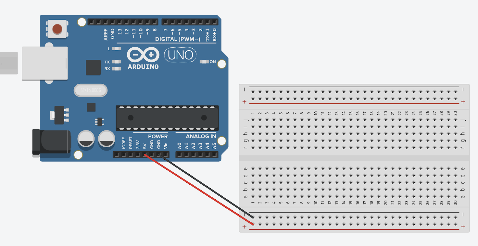
Step 1: Connect the Arduino board with the breadboard
Use 2 jump wires to connect the Arduino board with the breadboard. The pin with 5V connects to the “+” bus, the “GND” pin connects with the “-” bus.
Note: Here we are using Arduino as a power supply to generate 5 Volts. There are 2 important pins: “5V” and “GND”(abbreviation for ground). These are what you will be using as your power and ground terminals. 5V is the pin supplies 5 volts of power to your projects, which is a common value for digital electronics. There are a few ground pins on the Arduino and they all work the same.
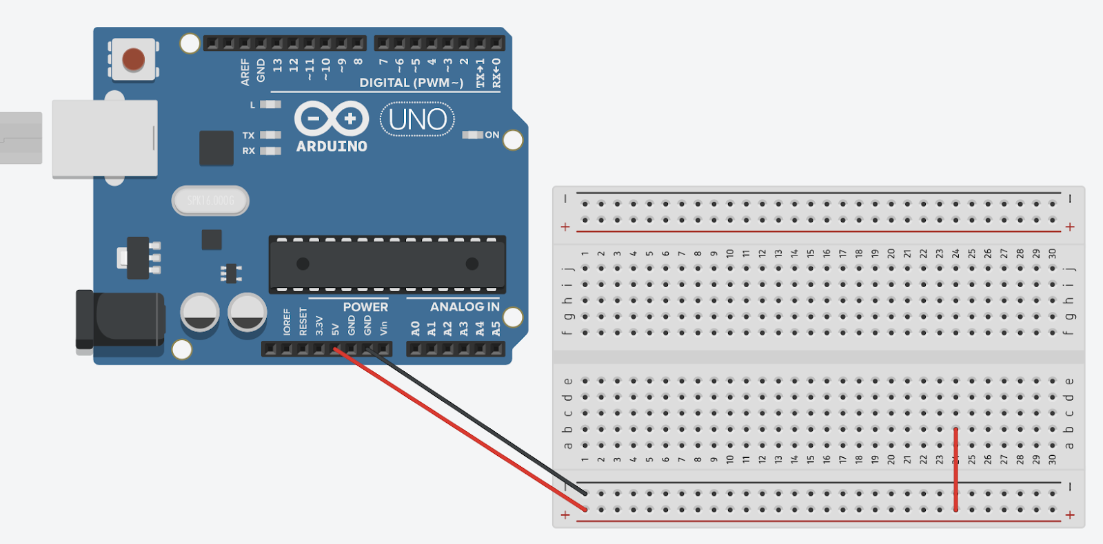
Step 2: start with a red Jumper
Land one side onto the positive bus; Connect another side to any empty row.
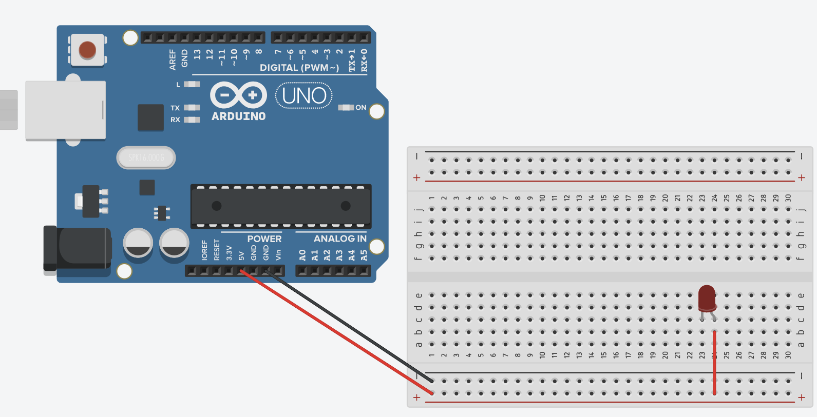
Step 3: Add LED
Long leg connected to the same row as red jumper, other leg can land in any other free row.
Step 4: Add 220 Ohm Resistor
One leg lands in same row as short LED leg. Other Leg lands in the negative bus
Step 5: Test the Circuit
Click “Start Simulation”, which means to connect the battery to the Arduino Board, and the LED in your circuit should light up!
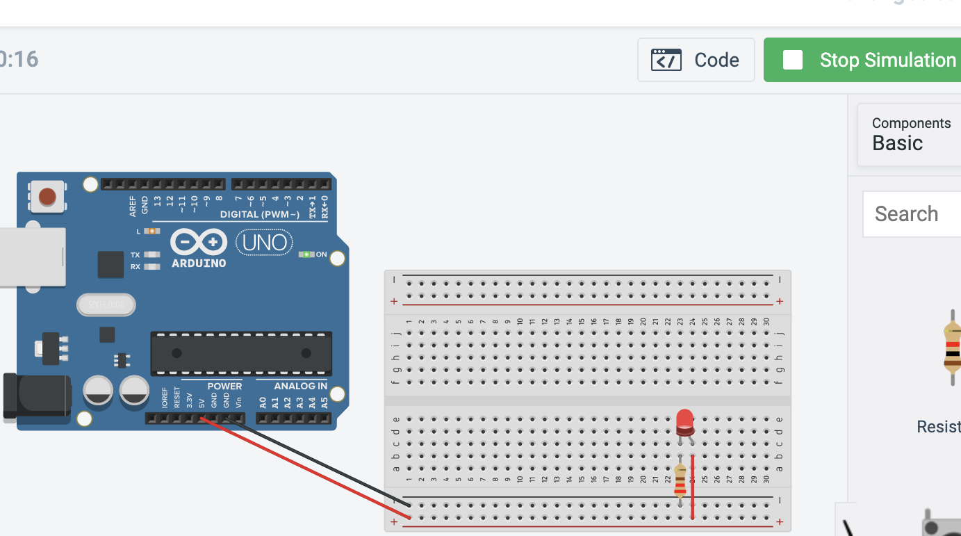
If not it is time for troubleshooting!
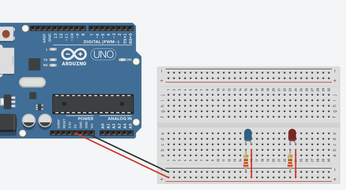
Bonus: Try to build a circuit with 2 LEDs!
Here is what that circuit could look like:
| Introduction |
| Lesson One: System Design |
| Lesson Two: Basic Circuitry Knowledge |
| Lesson Three: Electronics Tools |
| Lesson Four: Lighting an LED |
| Lesson Five: Tilt Switch |
| Lesson Six: Photoresistor and LED |
| Lesson Seven: Button with Piezo Speaker |
| Lesson Eight: Dimming an LED |
| Lesson Nine: Button Input for LED |
| Lesson Ten: Ultrasonic Sensor Alarm |
| Further Resources |