Photoresistor and LED
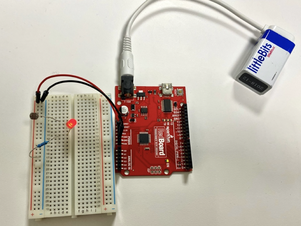
Sometimes you want to control the brightness of the LED according to the brightness of the room, so this circuit is there for you! Below is a photo of what it may look like if you build this circuit with an Arduino kit. We will build this step-by-step in TinkerCad Circuits:
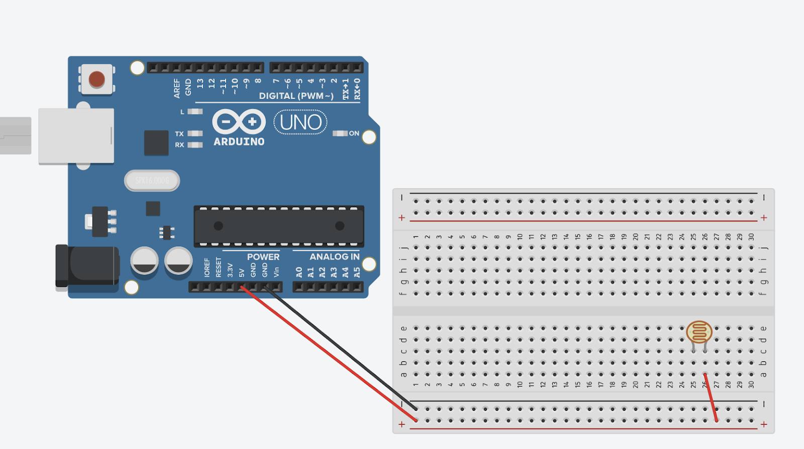
Step 1: Connect the Arduino board with the breadboard
Step 2: Connect circuits
Land one side of the photoresistor onto either positive bus, and connect another side to any empty row
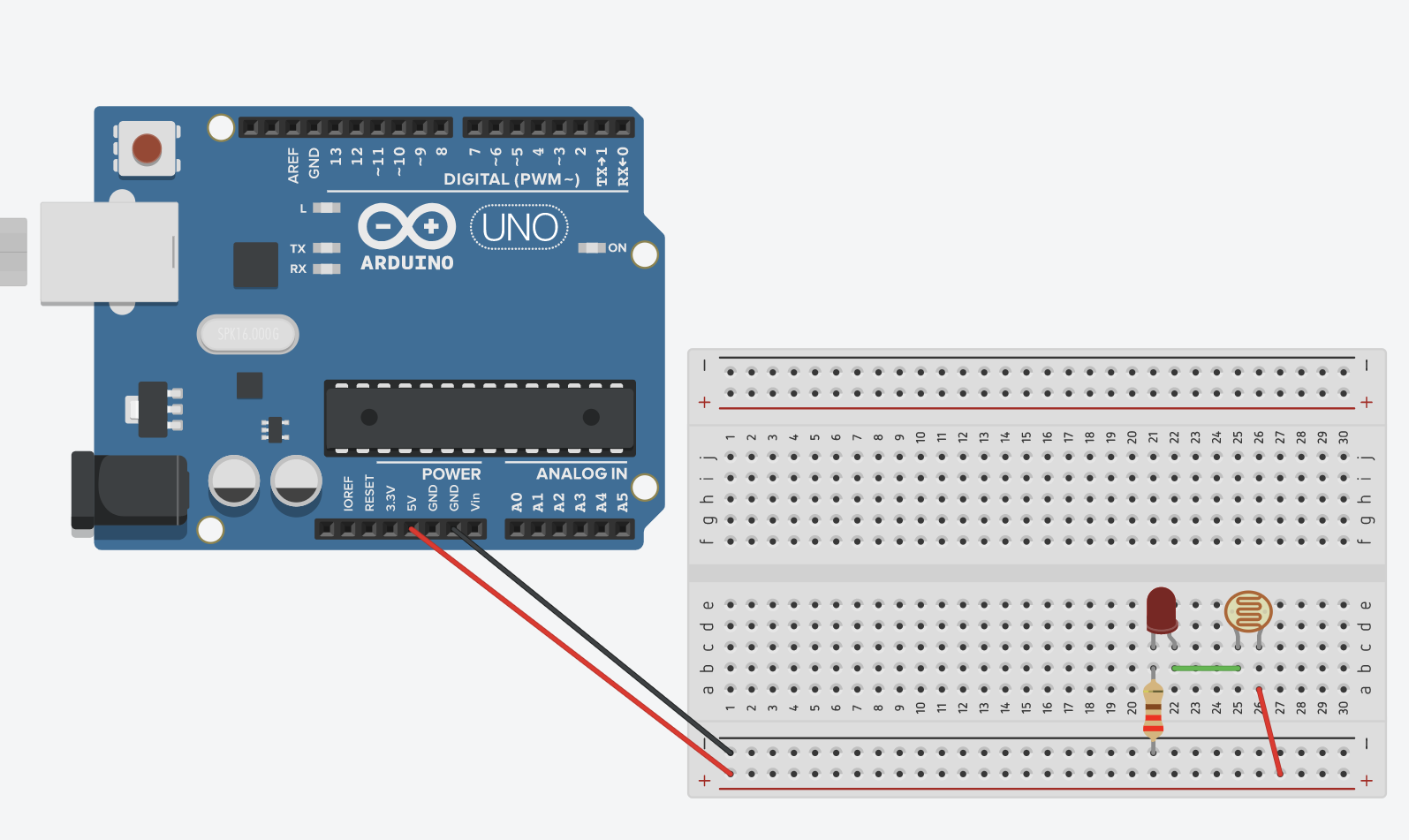
Step 3: Add LED
Long leg connected to the same row as the photoresistor Other leg can land in any other free row

Step 4: Add 220 Ohm Resistor
One leg lands in the same row as the short LED leg other leg lands anywhere in either negative bus
Step 5: Test your circuit
Click “Start Simulation”, your circuit should light up. The resistance of a photoresistor decreases with increasing light, so the LED will start off bright in a well-lit room!

| Introduction |
| Lesson One: System Design |
| Lesson Two: Basic Circuitry Knowledge |
| Lesson Three: Electronics Tools |
| Lesson Four: Lighting an LED |
| Lesson Five: Tilt Switch |
| Lesson Six: Photoresistor and LED |
| Lesson Seven: Button with Piezo Speaker |
| Lesson Eight: Dimming an LED |
| Lesson Nine: Button Input for LED |
| Lesson Ten: Ultrasonic Sensor Alarm |
| Further Resources |